Double Crimping Structure and the Name of Each Part
1. The name of each part of the first curling
1. The thickness of the first curling (Tc)
The thickness of the first curling refers to the thickness of the curling section after the can lid and the body are fitted, and the first rolling wheel is crimped to complete the first curling.
The thickness (Tc) of the first curling edge is affected by the size of the can lid’s round edge, the arc shape, the first curling roller groove and the pressure factors.
Tc=3tc+2tb+G′
tc: Thickness of iron for can lid
tb: Thickness of iron for can body
G’: The total thickness of the internal gaps of the first curling (usually 0.8-1.00mm, depending on the first curling groove shape, degree of newness or CH value)
Tc is usually controlled at 1.95-2.11mm
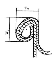
Figure 4-20 first step rolling
2. Width of first curling (Wc)
The width of the first channel curling refers to the width of the curling section after the completion of the curling
The curling width of the first track is affected by the size, shape, thickness of the iron sheet and the width of the first curling roller groove, etc., and it is usually controlled at 2.34 to 2.77mm. If it exceeds too much, the reason must be investigated.
Two
2. The name of each part of the second hemming
Figure 4-21 Schematic diagram of double crimping structure
1. Hemming thickness (T): the measured maximum size of each layer of iron in the hemming.
The curling thickness T consists of the thickness of the three-layer can lid and the two-layer can body. It is not parallel to the can body and forms an oblique angle of about 4°. It will be affected by the oblique angle of the outer edge of the indenter.
To
The curling thickness is usually affected by the groove shape of the second roller, the pressure of the second roller, the thickness and hardness of the tinned sheet, the type of sealing film and the amount of coating and other factors. The curling thickness T can be calculated by the following formula:
T=3tc+2tb + G (g1+g2+g3 + g4)
In the formula: tc is the thickness of the iron used for the can lid and Tb is the thickness of the iron used for the can body
G=g1+g2+g3 +g4 is the sum of the gaps of the iron sheets inside the crimping, which is approximately in the range of 0.10-0.40mm. Generally, G for φ63.5-φ98.9mm diameter tanks is 0.15mm. According to the actual situation, it is generally considered that G=0.15mm for water-soluble sealant and G=0.10mm for solvent-based sealant.
Regardless of the T value standard, the most important thing is that the thickness of the crimping in the same tank should be the same. No matter which type of tank is in the same tank, except for the joints (three-piece tank), the difference between the T values of any two points must not be greater than 0.08 mm.
2. Hemming width W: parallel to the measured size of the body cover hook
The hemming width is the width of the hemming section after the second seal is completed, also known as the hemming length. There are also standards for the crimping width W, which is generally based on the shape of the can lid forming part, the first track, the second roller groove shape and the crimping pressure, the pressure of the supporting chassis, the body hook and the thickness of the can body and lid, and the wear of the roller groove And other major factors.
Reference formula: W=1.1tc+BH+Lc+1.5tc
Where: tc—the thickness of the iron used for the tank cover BH—the length of the body hook Lc—the bottom gap
Usually W is 0.3-0.4mm larger than Wc, for example WC=2.6mm, W=2.9mm (reference value)
Generally, the curling width>3.05mm (except for φ153 large cans) is considered abnormal. Except for the seams in the same tank, the curling width of any two points must not be greater than 0.13mm, and the curling width must be greater than the countersunk degree C is smaller than 0.13mm, otherwise, when the two rollers are sealed, the lower edge of the curling width will be deformed due to no indenter support and the lower edge part cannot be pressed tightly.
The curling width W is regarded as one of the indexes of the tightness of the curling during the operation. Under the same conditions of the can lid, the body, and the roller, the larger W indicates the tighter the curling. During the sealing process, the usual situation W will become smaller and smaller, that is, the tightness will become looser. Generally, the variation of W can be used to evaluate the change in the tightness of the hemming.
3. Countersunk degree C
The countersunk degree is the depth measured from the top of the crimping to the shoulder blade adjacent to the inner wall of the crimping after the second round of crimping. It is also the position where the can lid and the indenter are engaged during crimping. The countersunk degree is affected by the thickness of the flange of the indenter, the countersunk degree of the can lid, the relative height of the roller and the indenter, the distance between the indenter and the supporting chassis, and the pressure of the supporting chassis. Usually the thickness of the flange of the indenter is 0.1mm deeper than the countersunk of the can lid, and the countersink of the crimping edge after rolling is 0.1mm larger than the thickness of the flange of the indenter (0.13-0.20mm)
Example: The countersunk degree of the can lid is 3.30mm
The thickness of the indenter flange should be 3.40mm
The gap between the second curling roller and the indenter is controlled within 0.10mm
The countersunk degree of the curling edge after the second volume seal C=3.50mm
The countersunk degree of most food cans is between 3.05-3.30mm;
The iron cans for carbonated beverages and beer have a depth of 3.80-4.06mm;
The vast majority of 211-diameter aluminum cans have a countersunk degree between 6.35-6.60mm;
209 iron bottom cans, 209 aluminum bottom cans, C is between 3.05-3.33mm.
There is no absolute standard value for the countersunk degree C, which is determined by the thickness of the indenter and the roller gap, but it must be 0.13mm-0.20mm larger than the crimping width W, and the countersunk degree of any two points in the same tank should not be more than 0.13. mm. …
4. Body hook length (BH)
The body hook length BH comes from the flanging of the can body. It is the length of the can body flanging. It depends on the fit between the lid and the can body, the width of the can body flanging, the radius of the can body flanging R, the pushing force and pressure of the supporting chassis. The distance between the head and the support chassis will change; if BH is too small, tank leakage is likely to occur; if BH is too large, the cover hook will become too small.
There is no absolute standard for body hook length BH. Most tank types use 1.9-2.05mm as the standard. As long as the overlap length and overlap rate can meet the safety sealing requirements, it can be accepted. Therefore, BH needs to increase with the tank type, and W increases. Big and increase. Under good rolling conditions, BH and CH are almost equal.
In the same tank, the difference between the BH values of any two points must not exceed 0.10mm, and the average value of the three tanks must not exceed 0.18mm. The greater the difference between this value, it indicates that the support plate is not parallel to the indenter or there is too much distance.
5. Cover hook length CH
The length of the lid hook CH refers to the bending length of the crimped part of the can lid inside the crimping, and the size of the crimping part of the can lid round edge can be changeable suject to the factor:the first track roller groove type, the first track roller pressure, the round edge arc shape of the can lid, the thickness of the indenter and other factors.
The cover hook length CH is the same as BH. It has different requirements according to the can diameter and varies from the width of the crimping. Generally, CH is 1.80-2.00mm, and usually the cover hook length CH must not be less than 1.65mm.
6. Cover hook gap (Upper gap) Uc, body hook gap (lower gap) Lc
The cover hook gap Uc and the body hook gap Lc are expected to be smaller in general cans. This is because the sealing film located in the crimping part moves to the crimping gap due to the pressure during the crimping process. Therefore, if Uc and Lc are too large, the sealing film will move to the gap and gather, instead of being firm, compressed, and isolated between the plates, resulting in poor sealing effect.
The Uc and Lc values increase mainly due to insufficient curling of the first track, excessive pressure on the second roller, and the lower jaw of the roller to cause the CH curl to sag. Compared to the hook groove of the first roller, the second roller has passed the hook groove. High, also due to the second curling rollers to make the CH curling droop, BH or CH is smaller.
7. Overlapping length OL
Crimping length refers to the length of the overlapping part of BH and CH inside the crimping
It can be approximated by the following formula:
OL=BH+CH+(1.1)tc-W
The splicing length is one of the criteria for judging the sealing performance of the can crimping. Usually, the splicing length <1.00mm is considered unacceptable (micro-sealing<0.76mm is unacceptable).
8. Overlap rate OL%
The overlap rate OL% indicates the degree of overlap between the BH and CH inside the crimp, that is, the percentage of the actual overlap length (a) to the theoretical overlap length (b). It is the most correct to calculate based on the actual measured values of the two parts a and b, and it can also be calculated approximately with the following formula
The overlap rate is also one of the criteria for judging the sealing performance of the can crimping. When the overlap rate is measured with a projector, the OL% must be >55%, and the formula calculation method must be >50%.
9. Tightness TR%
Lid hook wrinkle degree WR% refers to the degree of wrinkles on the inner edge of the lid hook after the crimping is disintegrated. It is visually graded according to the proportion of the wrinkled part to the length of the entire lid hook after the crimping is disintegrated. The number has increased. Tightness TR% and wrinkle WR% are in a corresponding relationship. The smaller the wrinkle, the higher the tightness. The wrinkle adopts ten-level method, and no wrinkle is 0. The tightness TR%=100%, and the wrinkle extends to the full cover. The elder is 10, and the tightness TR%=0%. It is usually judged by combining the flatness of the cover hook section as shown in Figure 4-22.
Figure 4-22 Tightness representation
Usually the tightness can be used to judge the sealing degree of the crimping or the adjustment of the sealing machine. When judging, the residual sealant on the lid hook should be removed, and the dent marks left by the removal should be calculated by the degree of wrinkle.
Several expression methods of crimp tightness are shown in Table 4-1.
Table 4-1 Tightness and Wrinkle Degree
10. The complete rate of inner lip, joint cover hook Jr%
For the part pressed out due to poor involvement of the cover hook, the cover hook becomes shorter and droops, which is called the inner drooping lip, as shown in Figure 4-23
Figure 4-23 – visual inspection of hook integrity of seam cover
The inner drop lip usually occurs at the joint, because the thick sheet iron at the joint often prevents the curling edge of the can cover from being drawn into the corner radius of the body hook like other parts, resulting in the drop lip. Serious external sagging or too thick welding seam and poor lap joint are enough to cause internal sagging, which will lead to leakage of the tank. After the disassembly of the curling edge, the proportion of the effective cover hook of the inner lip sagging of the cover hook to the width of the whole cover hook is expressed by naked eye or magnifying glass, and each drop is 25%. Due to the reduction of the thickness of the joint, the integrity rate of the joint cover hook is not the main problem Question.
11. Indentation
After the edge is disassembled, there is a mark of indenter line (angle change) around the inner edge of the can body (contact part with the cover), which is called pressure mark, and appropriate indentation must be formed. Figure 4-24
Figure 4-24 body indentation