Diagram of Measurement Method for Related Dimensions of Empty Tank
The seaming inspection must not only observe the corrugation on the hook part of the cover and measure the external data, but also observe the shape and position of the body hook and cover hook in the seaming cross-section. According to experience, it is absolutely not necessary to take the data measured on the outside of the curling as all the basis for evaluating the quality of the empty can.
In the inspection of double seaming, some items can be evaluated by appearance; some items need to use the corresponding micrometer and measuring instrument; some items need to be dissected and destroyed according to the regulations in order to obtain comprehensive test data and make a complete evaluation.
(1) Inspection position: points 1, 2 and 3 (and lap joint) in Figure 4-40
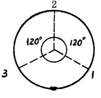
Figure 4-40 – detection position of round can
(2) Inspection tools: seaming micrometer, vernier caliper
(3) Inspection method:
External inspection
① Can height (H)
The vernier caliper is used to make the main ruler parallel to the can body. The height of the can that is measured is accurate to 0.02mm. Generally, the height of the empty can H should be ± 0.30mm, and the height of the large can with stiffeners should be ± 1.00mm.
② Seaming thickness (T):
Place the loosened micrometer on the top of the double seam so that the seam is balanced between the measuring anvil and the measuring shaft screw. Press and hold the micrometer with the index finger instead of the end of the micrometer, so that the anvil surface of the micrometer is at the same oblique angle with the inner side of the countersink, and the fit is good. Rotate the micrometer sleeve clockwise until the seam is tightly clamped between the measuring surface and the measuring screw. The micrometer sleeve should be made to fit, not too tight, and then read correctly. Each seam shall be measured at least three times, and the measured data shall be filled in the corresponding form.

Figure 4-41 – measuring the thickness of the seam
③ Seaming width (W)
Hold the micrometer with your thumb to make it stick to the can wall smoothly, turn the micrometer sleeve clockwise until the seam width is tightly clamped between the measuring anvil and the measuring sleeve screw, then read correctly, and fill the measured data in the corresponding table.
④ Burying degree (c)
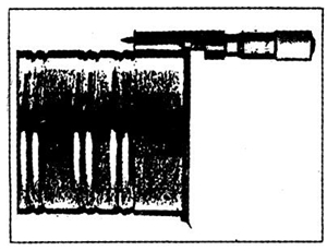
Figure 4-42 – measuring the length of seam
The correct value of C can be read out by placing the measuring instrument on the measuring position. If the curling micrometer is used for measurement, the protruding part of 5mm can be used for measurement, and the result is 5mm – the measured value is the depth of countersink (the protruding part should be placed on a hard plane to correct the error before measurement)
The first step is to put the instrument on the reference plane; the second step is to loosen the fastening screw of the dial and turn the dial knob to make the pointer point to “0”; the third step is to repeat the first step to correct the “0” reading, as shown in figure 4-43.
Measuring steps of countersink:
The first step is to place the countersink measuring instrument on the bottom of the empty can; the second step is to read out the data, that is, the dial reading plus the revolution; fill the data into the corresponding inspection report, as shown in figure 4-44
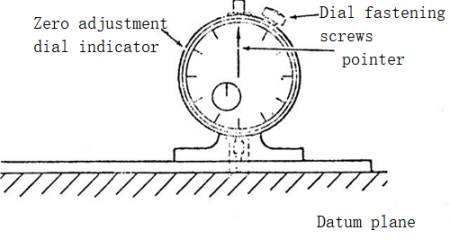
Figure 4-43 “0” point correction of countersink tester
The measuring position of the countersink is shown in figure 4-44.
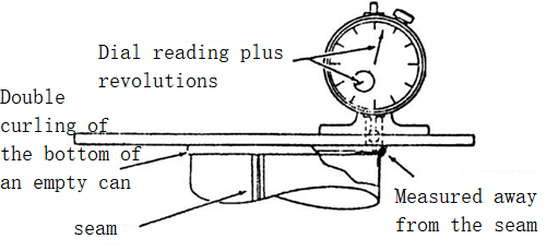
Figure 4-44 – Measurement of countersink
(5) Vertical collimation D (droop of seam at joint): first measure the widest droop Part D at joint, record the value, and then measure the nearest minimum seam width W, with D / W recording ratio, generally ≤ 20%.
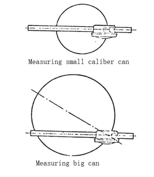
Fig. 4-45 measuring position of countersink measuring instrument
Internal examination (anatomical examination of seam)
For internal inspection and measurement, magnifying glass, optical projector or video measuring instrument should be used. Each can sealing machine should take samples at least once every two hours according to the regulations. First dissect the samples, and then take measurements or take samples at least four times per shift. When a machine stops running for a long time, it should start again as soon as possible (generally after running for 1-2 minutes, once the machine is hot) Destructive anatomical test was performed.
On site inspection
(1) Tools used: sanitary can opener, flat tongs, crimping micrometer or vernier caliper
(2) Anatomical examination procedure:
① Open a hole at the center of the can surface 6mm (1 / 4 “) from the curling edge with a sanitary can opener. Figure 4-46.
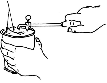
Figure 4-46
② Cut and dissect the curl on the opposite side of the seam with an electric rotary saw or a hand saw. See figure 4-47
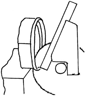
Figure 4-47
③ At the place 25.4mm (1 “) away from the sawing cut, use a pair of flat tongs to cut the 6mm bottom cover iron left by the cover along the inner wall of the seaming edge. See Figure 4-48
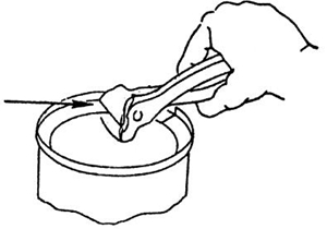
Figure 4-48
⑤ Tap gently along the edge of the can with pliers.
④ It needs skillful operation skills to hold the cover iron with a pair of flat tongs and tear the remaining bottom cover iron along the inner wall of the curling edge. Experience has proved that it is easy to tear the bottom cover iron by using a special pair of flat tongs against the upper edge of the curling edge, and continue to pull until the sawing incision. See figure 4-49
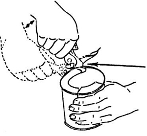
Figure 4-49
⑥ In a clockwise direction, disconnect 7 / 8 of the body hook from the cover hook of the whole curling edge from the sawing incision. Be careful not to damage the hook body, so that the cover hook is connected to the curling edge and will not fall off. See Figure 4-50
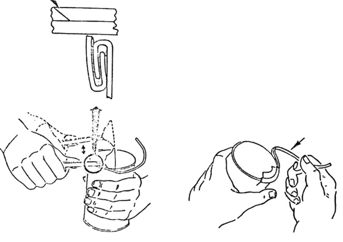
Figure 4-50
(3) Visual inspection
1) Cover hook: ① joint cover hook integrity rate (JR%) – Lip drop (ID)
(2) tightness (TR%) – wrinkle (WR%)
(3) appearance defects: skipping seal, false seal, folding, quick opening
2) Body hook: ① indentation pr
② Appearance defects: overlapping width and thickness of joints, welding tailing, edge cracking
(4) Metrological Inspection
1) Body hook (BH): ① measure to 0.02mm with vernier caliper
(2) measure to 0.01mm with seam micrometer
The measured value should be within ± 0.15mm of the standard value.
2) Cover hook (CH): tear off the corrugated side of the curling edge as the cover hook. In order to measure CH accurately, attention should be paid to the tearing action, and the integrity of the cover hook should be maintained to ensure the use of the micrometer. Measure it to 0.01mm with the micrometer and 0.02mm with the vernier caliper, and the measured value should be within ± 0.15mm of the standard value.
3) Overlap length (OL): calculated by formula according to measured data
4) Overlap rate (OL%)
① According to the measured data, the overlap ratio is calculated by the following formula.
Where: BH – body hook width
Ch – hook width
Tc – thickness of iron for bottom cover
TB – thickness of iron for tank body
W-seam width
② Check the calculation table of overlap rate according to the measured data
Steps of table checking:
Before looking up the table, the thickness of iron for can cover (TC), the thickness of iron for can body (TB), the width of cover hook (CH), the width of body hook (BH) and the width of seaming (W) must be measured, and the values of TC + TB, 2TC + TB and BH + CH must be calculated respectively. Look up the table in the following order.
The first step is to find out the value of TC + TB from the top left of the table, and from this column down, find out the value of BH + CH in the column BH + ch.
The second step is to find out the 2TC + TB value from the top right of the table. From this column to the left, the W value is found in the w column. If there is no corresponding value in the table, the latest value can be taken.
Finally, according to the above two values, it extends to the right and down to the column of overlap rate, and the value listed at the intersection is the overlap rate.
For example: TC = 0.23 TB = 0.23 BH = 1.93 ch = 1.90 w = 2.92
According to TC + TB = 0.46, this number is found in the fourth column from the upper left column of the table, and BH + CH = 1.93 + 1.90 = 3.83 is found down.
According to 2TC + TB = 0.69 ≈ 0.70, find this number from the upper right column of the table, and find w = 2.95 to the left.
From the intersection of 3.83 and 2.95, that is, the overlap rate = 54%
2. Quality control: projector inspection method (arbitration method)
(1) Instruments used: ① seam saw; ② seam projector
(2) Methods: first, the opposite point of the can joint was aligned with the seam saw;
② Cut off the sawn seam cross-section;
③ It is placed in the observation port of the projector;
④ Ol (and ol%) were measured directly on the projection screen;
⑤ Tear off the cover hook and visually check the completeness (JR%) and tightness (TR%) of the joint cover hook
(3) And check the following defects
① Body hook too long
The body hook length exceeds the specified size (Fig. 4-51).
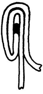
Figure 4-51 Body hook is too long
The possible reasons are as follows:
1) The tray pressure is too high.
2) Pin gauge (pin gauge adjustment) height is not correct. The position of the seaming chunk to the tray is too low (pin gage) is a gauge specially used to measure the distance between the seaming chunk and the tray during adjustment. In Japan, it is called sealing chunk height gauge (SCH)).
3) Mushroom flanging.
② The hook is too short
The body hook length is less than the specified size (Fig. 4-52).
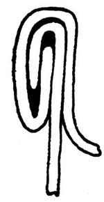
Figure 4-52 The body hook is too short
The possible reasons are as follows
1) Insufficient tray pressure
2) Improper adjustment of pin gauge height. The position adjustment of the seaming chunk to the tray is too high.
3) The first operation roller is too tight.
4) The adjustment of the second operation roller is too loose.
5) The flanging of can body is not good (the flanging is too short).
③ Cover hook too long
The length of the cover hook is greater than the specified size (Fig. 4-53)
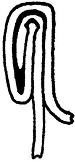
Figure 4-53 The cover hook is too long
The possible reasons are as follows
1) The first operation seal is adjusted too tightly.
④ Cover hook too short
The hook length is less than the specified size (Fig. 4-54).
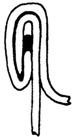
Fig. 4-54 – cover hook too short
The possible reasons are as follows
1) The curl edge of the can cover is not up to the requirement.
2) The adjustment of the first operation roller is too loose.
3) The tray pressure is too high.
4) The groove of the first operation roller is worn.
5) countersink is too deep.
⑤ Insufficient overlap length
When the body hook and the cover hook are hooked together, the overlapping length is insufficient when they are less than the specified size (Fig. 4-55).
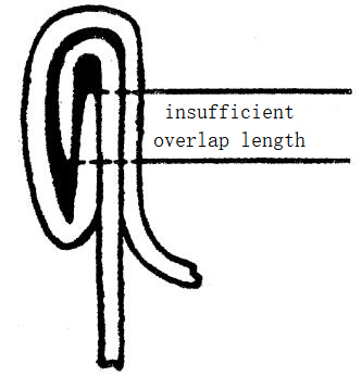
Figure 4-55 – insufficient overlap length
The possible reasons are as follows
1) The flanging of can body is out of specification.
2) The curl edge of the can cover is out of specification.
3) Poor adjustment of sealing machine.
⑥ Too tight seam of the first operation
When the first operation seaming is too tight, the bottom of the seam will be slightly flat throughout the whole length, with sharp edges and bad cover hooks (Fig. 4-56).
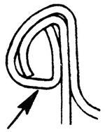
Figure 4-56 Too tight head curling
The possible reasons are as follows
(1) Improper adjustment of the first operation rollers (too tight).
(2) The groove of the first operation roller is too narrow.
⑦ Too loose curl on the first operation seam.
When the first operation seam is too loose, the lid hook does not contact the can body, and the curling edge of the can lid cannot be fully involved to form a good lid hook and overlapping length (Fig. 4-57).
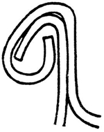
Figure 4-57 Too loose head curling
The possible reasons are as follows
(1) Improper adjustment of the first operation sealing roller.
(2) The profile of the first operation sealing roller is worn.
(3) The roller cam or stick is worn.
(4) Wear of roller pin or bearing.
(5) The groove of the first roller is too wide.
⑧ The second operation seam is too tight
If the pressure of the second operation seam is too high, it will not produce good seam, and it will make the sheet metal extend, so that the width (height or length) of the seaming will increase and the uncoupling or overlapping length will decrease (Fig. 4-58). This kind of seam is easier to crack than that formed by normal pressure seaming. If the secondary seaming is too tight, it will produce sharp edge and extrude the sealant from the seaming. The possible causes are as follows:
(1) Poor adjustment of the second operation rollers.
(2) The thickness of can body and / or cover iron is not proper (too thick).
⑨ The second seam is too loose
If the secondary seaming is too loose, the double seaming with cracks and leaks will occur, because the layers of folded iron sheet are not fully pressed together, and the sealant is not pressed to fill the gap in the curling (Fig. 4-59). The possible reasons are as follows
(1) Poor adjustment of double sealing roller.
(2) The double sealing roller is worn.
(3) The cam or inserting rod of the sealing roller is worn.
(4) The pin or bearing of sealing roller is worn.
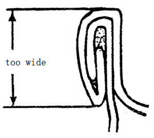
Fig. 4-58 – Secondary operation seam too tight
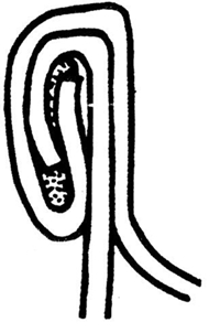
Fig. 4-59: the second operation seam is too loose